—— From Basic Concepts to Fine-Tuning, for Smooth and Sturdy Articulated Models
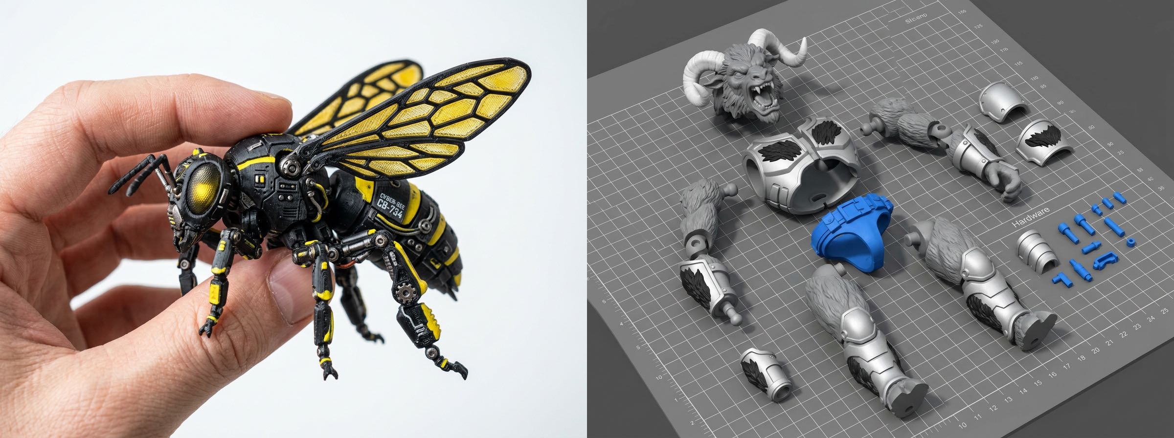
Connectors are the “skeleton” of articulated models, determining joint mobility, assembly fit, and finished piece durability. This tutorial will walk you through basic operations to advanced settings to configure connectors for different needs.
I. What Are Connectors?
Connectors are structures used to join different parts after model segmentation. Hi3D includes three built-in types to suit different use cases:
| Type | Core Features | Recommended Use Cases |
|---|---|---|
| Ball Joint | Multi-directional rotation for versatile posing | Action figures, character models requiring adjustable poses |
| Pin/Rivet | Single-axis rotation with a simple, stable structure | Limbs, wings, and other unidirectional moving parts |
| Sunmao (Mortise and Tenon) | Fixed connection after assembly, no looseness | Static figurines, display pieces |
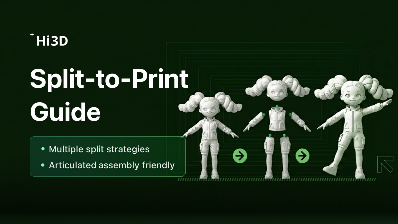
II. Basic Operation: One-Click Connector Generation
- Enter the Split-to-Print feature and import your segmented model (character or general model).
- Click “Add Connectors” and select your preferred connector type.
- The system will automatically generate corresponding structures between parts. Preview the results directly.
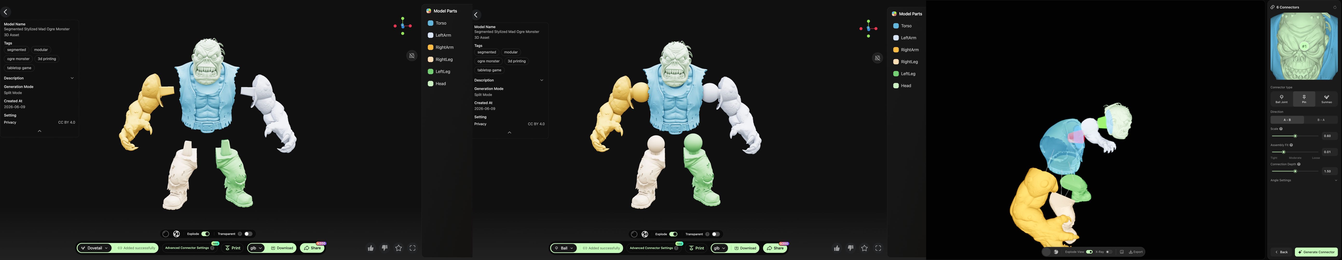
- To quickly check connection status, enable these two view modes:
- Explode View: Separates parts along connection points, allowing you to clearly see the position and spacing of each joint.
- Transparent View: Displays the model shell semi-transparently, making internal connectors easy to visualize.

III. Core Parameter Guide: Customizing Connectors for Your Model
One-click generation may not perfectly fit every model. Optimize results by adjusting these parameters:
Connector Scale
- Default value 0.6: Connector diameter matches the helper face (suitable for most scenarios).
- Increase: Connectors become thicker for stronger connections, but ensure they do not exceed part boundaries to avoid print failures.
- Decrease: Suitable for smaller parts, preventing connectors from penetrating the model shell.
Assembly Fit (Clearance)
- Bidirectional gap setting that directly affects assembly difficulty and finished stability.
- Increase clearance: Easier assembly, smoother part movement, but higher risk of loosening or detachment.
- Decrease clearance: Tighter connections prevent loosening, but overly tight settings can cause parts to jam or fail to fit.
- Recommended range: 0.02~0.1. Beginners are advised to start with the middle value 0.04.
Connection Length (Ball Joint Only)
- Refers to the distance from the ball center to the part surface.
- Increase: Connectors extend deeper into opposing parts for higher connection strength, ideal for large-scale models.
- Decrease: Shorter connectors work better with thin parts or space-constrained designs.
Angle Settings
- Tilt Angle (°): The angle at which the entire connector tilts around the insertion direction (0~45°). Used for angled surfaces to align connectors perpendicular to the mating plane, ensuring smooth assembly after printing.
- Tilt Direction (°): Rotation around the insertion direction to select the tilt orientation (0~360°). Only effective when Tilt Angle > 0.
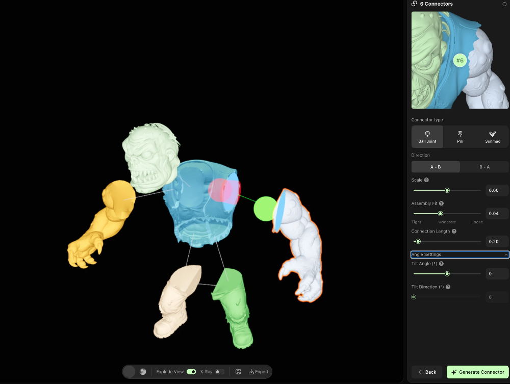
IV. Advanced Editing: Fine-Tuning in Hi3D Studio
If automatically generated connectors have incorrect positions, directions, or shapes, refine them in Studio:
- Click Advanced Connector Settings to enter the Studio connection structure editing page.
- Use Explode View and X-Ray (Transparent View) in the left viewport to inspect all connector positions.
- Adjust individual connectors in the right-side parameter panel:
- Change connector type (Ball Joint / Pin / Sunmao)
- Adjust connection direction (A→B or B→A)
- Modify Scale, Assembly Fit, Connection Length, and other parameters independently
- Delete unnecessary or incorrectly positioned connectors
- Click Generate Connector to update the structure after adjustments. Export the model once preview results are satisfactory.
V. Common Issues & Solutions
| Problem | Possible Cause | Solution |
|---|---|---|
| Parts cannot be assembled / jammed | Insufficient clearance, incorrect connector direction | Increase Assembly Fit clearance, or adjust connector direction/tilt angle |
| Loose parts / detachment after assembly | Excessive clearance, overly short connectors | Decrease Assembly Fit clearance, increase Connection Length or Scale |
| Connectors penetrate the model | Excessive Scale, overly thin parts | Reduce Scale, or adjust connector position in Studio |
| Cannot assemble angled surfaces | Connectors not perpendicular to mating plane | Enable Tilt Angle to align connectors perpendicular to the mating surface |
VI. Quick Setup Recommendations
| Model Type | Recommended Connector Type | Core Parameter Reference |
|---|---|---|
| Action Figure (Limbs) | Ball Joint | Scale 0.6 / Assembly Fit 0.04 / Connection Length 0.2 |
| Static Figurine (Full Body) | Sunmao | Scale 0.7 / Assembly Fit 0.02 |
| Wings / Mechanical Arms (Unidirectional) | Pin | Scale 0.5 / Assembly Fit 0.03 |
Pro Tip: After adjusting parameters, export a small-scale test print first to verify assembly fit before full-scale printing, avoiding material waste.