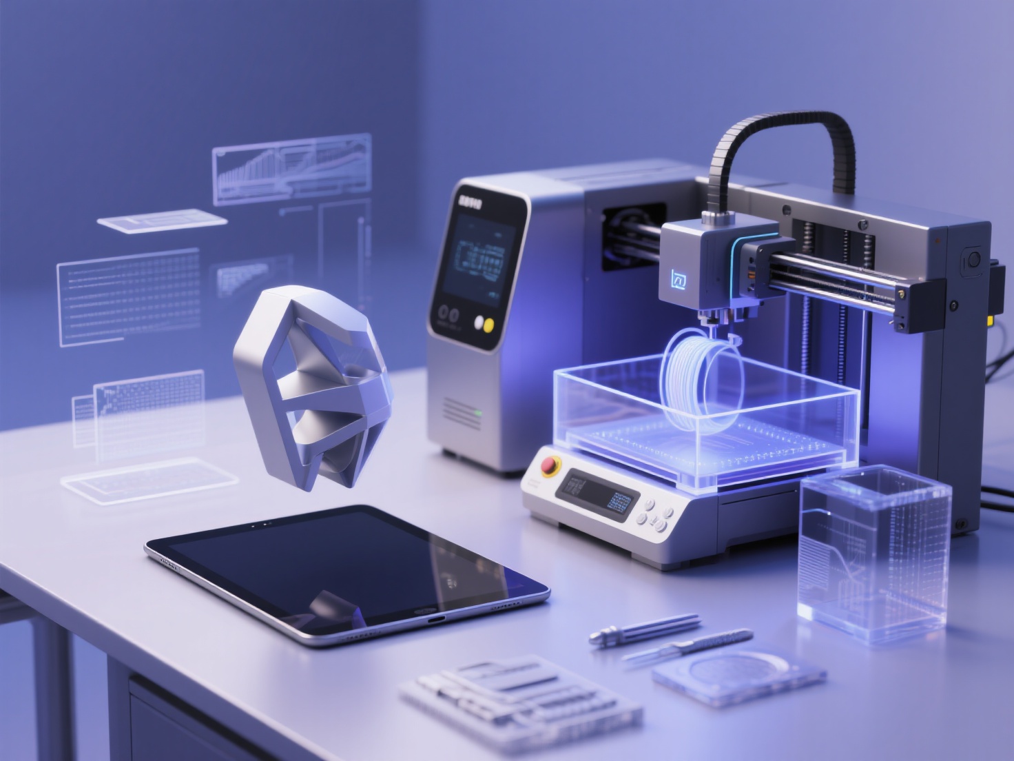
Transitioning from digital, screen-based 3D design to the physical world of additive manufacturing is an exciting milestone. However, a model that looks flawless in software like Blender or ZBrush can quickly turn into a pile of plastic spaghetti on the print bed if it isn’t properly prepared. In the digital realm, gravity doesn’t exist, and zero-thickness surfaces are perfectly acceptable. In the physical world, physics reigns supreme.
If you want to successfully bring your digital creations to life, you must learn how to design for 3D printing. By mastering essential 3D print design rules, you can avoid failed prints, save time, and reduce material waste. Whether you are creating intricate art sculptures, functional mechanical parts, or tabletop miniatures, learning to optimize a 3D model for printing is a non-negotiable skill.
In this comprehensive guide, we will explore the critical constraints of additive manufacturing and provide practical tips to elevate your 3D modeling for printing workflow.
What is Design for 3D Printing?
Design for 3D Printing (often referred to as DfAM, or Design for Additive Manufacturing) is the process of creating and adapting digital 3D models to meet the specific physical constraints of 3D printers, ensuring structural integrity, dimensional accuracy, and successful printability.
By anticipating how a printer deposits material layer by layer, designers can optimize geometry to minimize the need for support structures, ensure moving parts fit together perfectly, and guarantee the final object is both aesthetically pleasing and physically robust.
Crucial 3D Print Design Rules You Need to Know
To create physical objects from digital files, every designer must adhere to a set of universal guidelines. Here are the foundational rules you must master.
1. Minimum Wall Thickness
Unlike digital assets used in video games or animations, a physical model must have volume and thickness. If a wall is too thin, the slicing software will either ignore it, or the printer will produce a fragile structure that easily snaps.
- FDM Printers (Fused Deposition Modeling): A standard FDM nozzle is 0.4mm wide. Therefore, your absolute minimum wall thickness should be 0.8mm (equivalent to two perimeter lines). For parts requiring structural strength, aim for 1.2mm to 1.6mm.
- SLA Printers (Resin): Resin printers can achieve much higher details. The minimum wall thickness can be pushed to 0.5mm, provided the wall is properly supported.
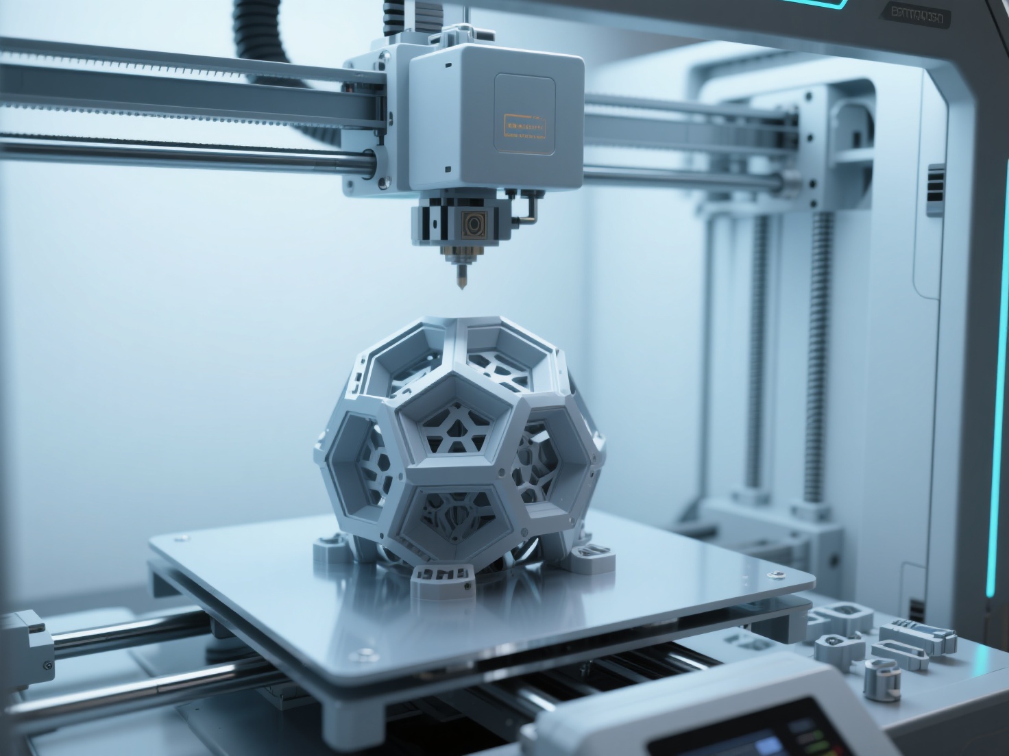
2. The 45-Degree Rule for Overhangs
Because 3D printers build objects layer by layer from the ground up, they cannot print in mid-air. An overhang is any part of a model that extends outward beyond the layer below it.
- The Golden Rule: Any overhang exceeding 45 degrees from the vertical axis will typically require support structures.
- Why avoid supports? Supports consume extra material, increase print time, and leave rough marks on the surface of your model that require post-processing (sanding and smoothing). Whenever possible, design chamfers (sloped edges) instead of fillets (rounded edges) on the underside of your model to keep angles under 45 degrees.
3. Bridging Across Gaps
A “bridge” occurs when the printer must extrude material across a gap between two elevated points without support underneath.
- Most modern FDM printers can successfully bridge gaps of up to 10mm to 15mm depending on the cooling fan speed.
- If your design requires a gap wider than this, you will either need to generate support structures or redesign the part using an arch or a teardrop shape to make it self-supporting.
4. Tolerances for Assembly and Moving Parts
When designing mechanical parts, hinges, or interlocking pieces, you must account for the slight expansion of heated plastic (or curing resin) as it settles. If you model a 10mm peg to fit perfectly into a 10mm hole, it will not fit.
- Tight Fit (Friction/Press Fit): Leave a 0.15mm to 0.2mm gap between the parts.
- Loose Fit (Moving or Sliding Parts): Leave a 0.3mm to 0.5mm clearance between the components to ensure they move freely without fusing together.
5. Hole Compensation
Due to material shrinkage and the way slicing software calculates paths, printed holes almost always come out slightly smaller than their digital dimensions.
- Pro Tip: If you need an exact hole for a screw or a metal rod, artificially enlarge the hole in your CAD software by 0.1mm to 0.2mm, or plan to drill the hole out to its final dimension after printing.
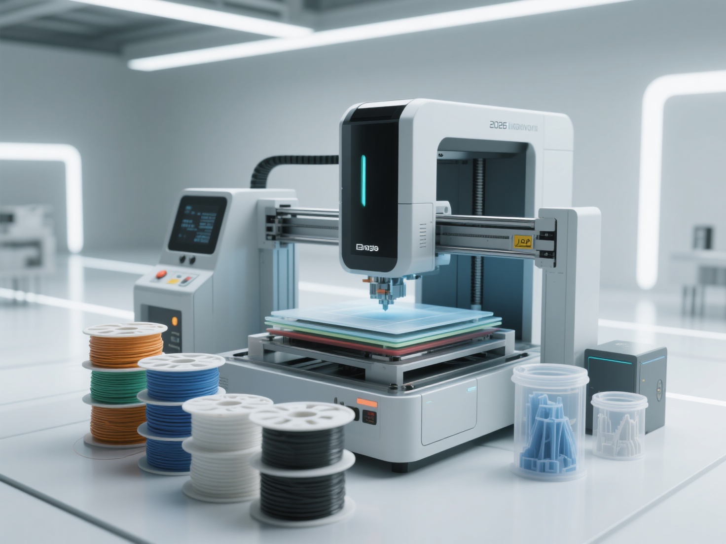
Designing for Different Technologies: FDM vs. SLA
When you optimize a 3D model for printing, you must tailor your design to the specific hardware you are using. Fused Deposition Modeling (FDM) and Stereolithography (SLA/Resin) require vastly different mindsets.
Hollowing and Escape Holes (For Resin Printing)
Resin printing produces solid, heavy objects by default. Printing a large solid block of resin is not only expensive but creates massive “peel force” suction against the FEP film, which often leads to print failures.
- Hollowing: Always hollow out large resin models. A wall thickness of 2mm to 3mm is usually ideal for medium-sized statues or parts.
- Escape Holes: A hollowed model must have escape holes (drainage holes). Without them, liquid resin trapped air will create a vacuum cup effect, tearing the print off the build plate. Place at least two holes (minimum 2mm in diameter) near the base of the model where they won’t be visible.
Orientation and the Z-Axis Weakness (For FDM Printing)
FDM prints are inherently weaker along the Z-axis (the vertical direction) due to the layer lines.
- Strength Planning: Never design a thin, load-bearing part (like a peg or a joint) pointing straight up in the Z-axis, as it will snap easily under lateral pressure. Design the model so that stress is applied perpendicular to the layer lines.
- Flat Bases: Ensure your model has a sufficiently large, flat base to adhere firmly to the print bed, preventing warping or detachment mid-print.
Design Rule Comparison: FDM vs SLA
| Design Feature | FDM Constraints (Filament) | SLA Constraints (Resin) |
|---|---|---|
| Min. Wall Thickness | 0.8mm - 1.2mm | 0.5mm - 1.0mm |
| Max. Unsupported Overhang | 45 Degrees | 15 - 20 Degrees (Requires dense supports) |
| Bridging Distance | Up to 15mm | Not recommended (Requires supports) |
| Tolerance for Assemblies | 0.2mm - 0.4mm | 0.1mm - 0.2mm |
| Hollowing Required? | Usually handled via Infill in slicer | Mandatory for large models (Include escape holes) |
Best Practices to Optimize Your 3D Model for Printing
Before exporting your final file, run through this essential design checklist:
- Ensure “Watertight” Geometry: Your model must be a single, solid “manifold” mesh. Remove any intersecting internal faces, floating vertices, or holes in the surface. Slicers cannot interpret non-manifold geometry.
- Apply Proper Scaling: Double-check your units (millimeters are standard for 3D printing). Exporting a model in meters can cause it to appear microscopic in your slicer.
- Choose the Right Format: While STL has been the industry standard for decades, OBJ, GLB, and 3MF formats are vastly superior today. They retain more data, support colors, and result in smaller file sizes.
Accelerate Your Workflow with AI Generation
While mastering these 3D print design rules is essential for manual modeling, starting from scratch can be incredibly time-consuming. Today, AI tools are revolutionizing the 3D modeling for printing workflow by allowing creators to generate highly accurate base meshes in seconds, which can then be refined in software like Blender.
If you are looking for a massive head start, Hitem3D is an invaluable tool for your arsenal. Built on the proprietary Sparc3D (high precision) and Ultra3D (high efficiency) models, Hitem3D is a next-generation AI platform that turns 2D images into production-ready 3D geometry.
Unlike early AI generators that produced messy point clouds or hollow shells, Hitem3D features groundbreaking Invisible Parts reconstruction technology. It intelligently infers and builds the hidden structures of a model, generating full-form, solid geometry with incredibly sharp edges—perfectly suited for physical manufacturing. With output resolutions reaching up to 1536³ Pro (2M polygons), the structural integrity and engraving precision are unparalleled.
Furthermore, Hitem3D completely streamlines the printing pipeline. Once your model is generated, you can use the one-click direct send feature to instantly export your watertight GLB, OBJ, or STL file directly to Bambu Studio or OrcaSlicer, bypassing tedious manual setup. If you aren’t satisfied with the first result, Hitem3D’s generous Free Retry system allows you to regenerate the model without spending extra credits.
Streamline Your 3D Print Design Workflow
Learning to design for 3D printing is a journey of trial and error. By respecting the physical limitations of your printer—adhering to minimum wall thicknesses, managing 45-degree overhangs, adjusting tolerances, and strategically planning your print orientation—you can drastically reduce failures and elevate the quality of your printed projects.
Remember, the goal is to work smarter, not harder. Combine your foundational knowledge of 3D print design rules with cutting-edge AI tools to accelerate your creative process.
Ready to transform your ideas into print-ready reality in a fraction of the time? Experience the power of AI-driven geometry generation with full Bambu Studio and OrcaSlicer integration today.
Frequently Asked Questions (FAQ)
1. What is the best file format to export a 3D model for printing?
While STL is the most common format, 3MF, GLB, and OBJ are heavily recommended today. 3MF and GLB files are smaller, more robust, support multi-color data, and are less prone to manifold errors compared to legacy STL files.
2. Why does my 3D model look fine on screen but fails in the slicer?
This usually happens because the model is “non-manifold” (not watertight). It may contain zero-thickness walls, internal intersecting faces, or holes in the mesh. You must ensure your model is a single, enclosed solid volume before slicing.
3. How do I optimize a 3D model for multi-color printing?
For multi-color FDM printing, the model needs cleanly defined separate shells or painted color regions. Advanced tools like Hitem3D offer Multi-Color Model Segmentation, which instantly and automatically segments AI-generated models into distinct, clean color regions with sharp borders, perfect for multi-color 3D printing.
4. Do I always need support structures?
No. You can avoid supports by strictly following the 45-degree rule, designing chamfers instead of steep curves, and orienting the model so that overhangs point upward. Designing “support-free” models is considered the gold standard in DfAM.